
Modern structural construction is based on reinforced concrete, which is the marriage between the tensile strength of steel and the compressive strength of concrete. The concrete reinforcement plan helps engineers and contractors produce detailed drawings so that the building structures are safe, long-lasting, and compliant with set codes.
The ability to read and develop a concrete reinforcement plan is an important skill posed to civil engineers, site supervisors, structural detailers, BIM modelers, and steel fixers. The communication medium between the design office and the construction site advises on the arrangement of the rebar position, bending, lapping, and tying to this end, such plans are utilized.
In this blog, we will walk you through what a concrete reinforcement plan is, how to make sense of symbols and notations, and how to make correct, ready-to-build concrete reinforcement drawings.
What Is a Concrete Reinforcement Plan?
A concrete reinforcement plan is a detailed set of construction drawings that describe the size, type, number, and location of steel reinforcement in concrete elements. It guarantees the custom fit of strength and serviceability demands of the structure, especially to bending, shear, torsion, and axial loads.
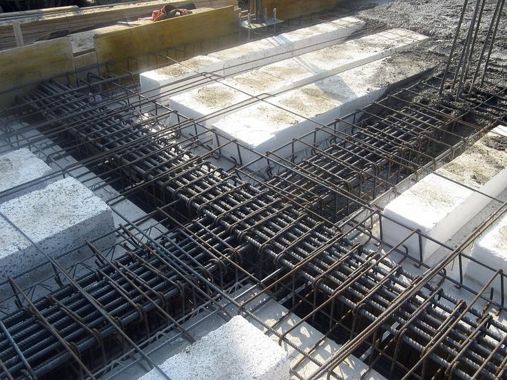
The concrete reinforcement plan typically includes:
- Structural layouts showing the geometry of beams, columns, slabs, and footings
- Bar schedules indicating type, size, spacing, and total lengths of rebar
- Bending details with hook lengths, shapes, and angles
- Section views illustrating the exact location of top and bottom bars, stirrups, and ties
- Notes and standards specifying design codes, cover requirements, and lap splice lengths
Key Symbols and Notations Used in Reinforcement Drawings
To properly read or create a concrete reinforcement plan, one has to get acquainted with the most widely used symbols, abbreviations, and notations that are used across the drawings.
These are some of the most common conventions in a concrete reinforcement plan:
1. Bar Marks and Sizes
- Bar markings on bars usually consist of individual bar marks (e.g., B1, T2), that are used to reference bending schedules.
- The sizes can commonly be given numbers (e.g., #4 in imperial, T12 in metric), where the number is the diameter of the bar.
2. Spacing Notation
- Commonly represented as: @150mm c/c i.e. spacing of rebar is 150 mm center-to-center.
- Bar orientations are indicated (eg, EW (each way) or T/B (top and bottom).
3. Rebar Shape Codes
- The specifications of the bending of the bar are through shape codes of either U, L, or Z codes.
- The bar bending schedules have these shapes, which are supported by detailed angles and length.
4. Section and Callout Symbols
- Circular or rectangular section markers refer to specific drawing sections.
- Callouts (e.g., “See Detail A”) point to enlarged views for clarity.
5. Cover and Lap Notes
- Notations for concrete cover (e.g., “Cover = 40mm”) ensure corrosion protection and fire resistance.
- Lap splice notes indicate minimum overlap lengths when bars are extended.
6. Legends and General Notes
- A legend provides visual reference for all symbols used.
- General notes list reinforcement standards (e.g., ASTM A615, BS 8666) and placement instructions.
It is based on understanding these factors that there is an interpretation or establishment of a concrete reinforcement plan. Being able to master these details can help the teams to get construction right with fewer slips, less expensive mishaps, and in accordance with the design intention and the codes.